Encoder Logic Diagram And Truth Table : Encoder Circuitverse / Difference between encoder and decoder.. 4.4.8, this type of decoder has 4 inputs for binary coded decimal and an output for each of the 7 leds that. On the contrary, a decoder accepts binary code as its input. The user inputs the output values in the x column it will be a chart much like this There are different types of decoders like 4, 8, and 16 decoders and the truth table of decoder depends. 3 to 8 decoder truth table:
When a logic gate has only two inputs, or the logic circuit to be analyzed has only one or two gates, it is fairly easy to remember how a. An adder is a digital logic circuit in electronics that performs the operation of additions of two number. Connect and share knowledge within a single location that is structured and easy to search. 4.4.8, this type of decoder has 4 inputs for binary coded decimal and an output for each of the 7 leds that. What is a priority encoder?
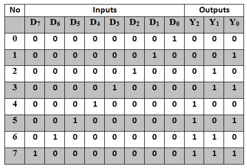
Encoder Logic Diagram And Truth Table Binary Encoders And Their Applications See The Best Latest Encoder Truth Table On Iscoupon Com Compustar Wiring Diagram from media.cheggcdn.com Now that we know how an encoder 4:2 encoder circuit diagram: Logical circuit of the above expressions is given below: How to draw the logic diagram for this? A 1 =y 3 +y 2 a 0 =y 3 +y 1. Truth table of an 8:3 encoder. Truth table of the encoder the decoders and encoders are designed with logic. We will discuss each herein and demonstrate ways to convert between them. 1 multiplexer combinational logic circuit | boolean algebra & logic gates.
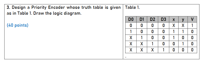
What is a priority encoder?
The 8 to 3 line encoder is also known as octal to binary encoder. The block diagram and truth table of a 4 input encoder is shown in below figure. 8 to 3 line encoder: Each row will have different predetermined values as the truth table normally would have. The full adder (fa) circuit has three inputs: The truth tables of logic gates are very complex but larger than the not gate. 1 multiplexer combinational logic circuit | boolean algebra & logic gates. You can enter logical operators in several different formats. Truth table is a mathematical table and the base for all computing needs. Truth table for 2 to 4 decoder similar to encoder design, vhdl code for 2 to. Difference between encoder and decoder. Truth tables offer a simple and easy to understand tool that can be used to determine the output of any logic gate or circuit for all input combinations. The truth table consists of four rows , since , it is assumed that only one input is the value of 1 then the corresponding binary code associated with that enabled input is displayed at the outputs.
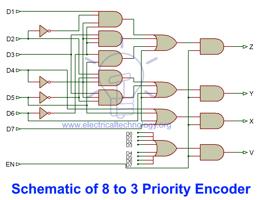
The logical expression of the term a0 and a1 is as follows: When logic gates are connected they form a circuit. 8 to 3 line encoder: An encoder is a device that converts the active data signal into a coded message format. How to draw the logic diagram for this?
Binary Encoders And Their Applications from www.electronicshub.org Note that the truth table (table 4.4.3) shows the appropriate high and low logic levels as 1 and 0 respectively to match the logic levels shown in the as shown in block diagram format in fig. Now that we know how an encoder 4:2 encoder circuit diagram: The truth table of 4 to 2 encoder is as follows Draw the truth table and logic gate diagram. Logic diagram of 2:4 decoder. Flip flops input equations and the circuit output are as follows; What is a priority encoder? An adder is a digital logic circuit in electronics that performs the operation of additions of two number.
Table i shows the truth table for the decoder of figure 1, which shows that when the enable is low, all the output lines are low, no matter what the input sequence is.
The logical expression of the term a0 and a1 is as follows: Does my truth table correct? Read about encoder (combinational logic functions ) in our free electronics textbook. A sequential circuit has two d flip flops a and b, two inputs x and y and one output z. Encoders are combinational logic circuits and they are exactly opposite of decoders. The circuit diagram of 4 to 2 priority encoder is shown in the following figure. Logic diagram of 2:4 decoder. Logical circuit of the above expressions is given below: The figure below shows the logic symbol of 4 to 2 encoder : Table i shows the truth table for the decoder of figure 1, which shows that when the enable is low, all the output lines are low, no matter what the input sequence is. Find 4:2 encoder, 8:3 encoder and 4:2 priority encoder circuit, truth table and boolean building encoders using combinational logic designs. We will study its working and see the truth table of 4x2 encoder and 2x4 decoder. Note that the truth table (table 4.4.3) shows the appropriate high and low logic levels as 1 and 0 respectively to match the logic levels shown in the as shown in block diagram format in fig.
Creating a truth table involves a simple logic yet sometimes it may slow you down, especially when you are working on a last minute project. There are different types of decoders like 4, 8, and 16 decoders and the truth table of decoder depends. Logic circuits are designed to perform a particular function, understanding the nature of that function requires a logic circuit truth table. Note that the truth table (table 4.4.3) shows the appropriate high and low logic levels as 1 and 0 respectively to match the logic levels shown in the as shown in block diagram format in fig. A 1 =y 3 +y 2 a 0 =y 3 +y 1.
Binary Encoder Construction Types Applications from www.electricaltechnology.org It is used to find out if a propositional expression is true for all legitimate input values. Read about encoder (combinational logic functions ) in our free electronics textbook. This indicates the off state of the decoder which can also be considered to be its reset state. Truth table for 2 to 4 decoder similar to encoder design, vhdl code for 2 to. There are different types of decoders like 4, 8, and 16 decoders and the truth table of decoder depends. Half adder and full adder. 3 to 8 decoder truth table: Encoder a block diagram b logical truth table c schematic.
From this truth table, the boolean expression for the encoder above with data inputs d0 to d7 and outputs q0, q1, q2 is given as
Each row will have different predetermined values as the truth table normally would have. The truth table of 4 to 2 encoder is shown below. The figure below shows the logic symbol of 4 to 2 encoder : This is a partial tt, to give an idea about the circuit. At any time, only one of these 4 inputs can be '1' in order to get the respective binary code at the output. The circuit diagram of 4 to 2 priority encoder is shown in the following figure. It is used to find out if a propositional expression is true for all legitimate input values. The 8 to 3 line encoder is also known as octal to binary encoder. It is to be observed from. When a logic gate has only two inputs, or the logic circuit to be analyzed has only one or two gates, it is fairly easy to remember how a. An adder is a digital logic circuit in electronics that performs the operation of additions of two number. Draw the truth table and logic gate diagram. A logic diagram uses the pictoral description of logic gates in combination to represent a logic expression.